


Current info-communications systems are designed by classical mechanics (Electromagnetism). If the rules of manipulating information are extended into quantum mechanics, one can realize unbreakable secure communications (quantum cryptography), super-parallel computation (quantum computation), and ultimately low-power high-capacity communications (quantum communications). Quantum cryptography reaches practical metropolitan-area network operations, however, the distance is limited within 100km. Quantum computation, now developed with various systems such as ions, superconductors, optics, etc, has yet to be practical. Quantum communications, which rely on a new receiver using quantum computation, called quantum decoder, still remain a demonstration at a two-bit level. If a node technology would be developed that can extend the distance of quantum cryptography as well as implement optical quantum computation, then quantum cryptography, computation, and communications could be integrated in a quantum-enhanced optical network. It has, however, yet to be made clear how such a universal node technology can be realized, which may be referred to as quantum node technology.
Home > Press Release > Successful Demonstration of Quantum Tele-amplification
~ Establishing Common Foundation to Long-distance Quantum Cryptography, Low-power High-Capacity Communications ~
The National Institute of Information and Communications Technology (NICT, President: Dr. Masao Sakauchi), in collaboration with Seoul National University, has invented and demonstrated a scheme, called “quantum tele-amplification”, that realizes noiseless teleportation of optical signals with an amplification gain between nodes in an optical network. This scheme can be used both for extending a distance of quantum cryptography and for processing signals to beat the capacity limit of optical communications, establishing a common foundation to long-distance quantum cryptography and low-power high-capacity communications. This result will be published in the June 2013 issue of “Nature Photonics”.
This research was partly supported by the Quantum Information Processing Project in the Funding Program for World-Leading Innovative R&D on Science and Technology (FIRST Program) in Japan, and by a National Research Foundation of Korea grant (No. 2010-0018295).
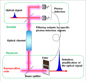
Quantum tele-amplification demonstrated this time would be a core of this quantum node technology. In the scheme, an optical signal is noiselessly amplified and transferred from the sender to the receiver, sharing a quantum superposition state of two coherent states encoding bits of 0 and 1 (Figure in right). This scheme has been known to be a basic quantum gate, and further shown this time to be used to extend the distance of quantum cryptography. Especially the scheme can tele-amplify coherent states which are the information carrier in current optical infrastructures, and hence can implement quantum decoder for them. By installing it into the optical infrastructures, low-power high-capacity communications can be realized. Our achievements open a door to integrate quantum cryptography, computation, and communications, those studied separately so far, into a quantum-enhanced optical network.
Our current setup of quantum tele-amplification is as large as a few meters square. Next step is to make it compact with integrated optics, and apply it to the implementation of quantum decoder and the extension of the distance of quantum cryptography. Eventually we will revise it for an interface technology to integrate quantum cryptography, computation, and communications into a quantum-enhanced optical network.
Appendix
Jonas S. Neergaard-Nielsen, Yujiro Eto, Chang-Woo Lee, Hyunseok Jeong, and Masahide Sasaki, DOI:10.1038 /NPHOTON.2013.101.
Among various implementations of quantum computing, coherent-state quantum computing (CSQC) is of special interest for enhancing the performance of optical communications, where information is encoded into coherent states. These are the only states that can be transmitted preserving the state purity even through a lossy channel. Hence, a simple classical encoding with coherent states can be the optimal strategy of the transmitter to achieve the ultimate capacity of a lossy optical channel. On the receiver side, the sequence of coherent-state pulses should be decoded fully quantum mechanically by employing a collective measurement with CSQC (Fig. 1). This scheme can realize communication with larger capacity, beating the conventional homodyne limit of optical communications (Fig. 2).


The principle of quantum decoder was first demonstrated in the laboratory by NICT in 2003, using photon polarization and path encoding (M. Fujiwara, M. Takeoka, J. Mizuno and M. Sasaki, "Exceeding classical capacity limit in quantum optical channel," Phys. Rev. Lett., vol 90(16), 167906 (2003).) Since then, no implementations of quantum decoder for practical signals of coherent states have ever been made. They require CSQC, however, only one-bit basic gate was realized, while implementation of two-bit basic gates is left open. The implementation of CSQC is the perquisite for the ultimately efficient low-power high-capacity communications. In particular, even in a small scale, quantum decoder can improve the communication performances step by step, when installed in front of classical decoder of an optical communications system. Thus CSQC and quantum decoder have practical impacts. Quantum tele-amplification demonstrated by us delivers a basic building block for CSQC.
In CSQC, bit information 0 and 1 is encoded with two coherent states α>, |-α>, which are two waves of laser light with phase difference of 180 degree. α is the amplitude of wave of coherent state. Quantum bit is its superposition of them c0|α>+c1|-α>.
In quantum tele-amplification invented this time, an input at the sender c0|α>+c1|-α> is amplified in its amplitude α with an gain g noiselessly, and is transferred to the receiver. In conventional amplification scheme, noises are inevitably added to the output signal, disenabling faithful transmission of quantum bit c0|α>+c1|-α>.
The basic scheme is depicted in Fig. 3. The receiver prepares another superposition state |β>-|-β> and splits it into beams B and C via a beam-splitter (BS). Beam C is then sent to the sender, where beam C is combined with the input state c0|α>A +c1|-α>A in beam A. The sender finally measures beams A and C by single-photon detectors. Then, when the sender’s detectors register a single photon at beam A and nothing at beam C, the receiver unambiguously restores the state c0|gα>+c1|-gα>. Thus by conditioning beam B on the sender measurement result, the receiver can restore the input state with the gain g.
The key ingredient in the scheme here is that the beam splitting of coherent superposition state |β>-|-β> generates a correlation called quantum entanglement. As shown in blue in Fig. 3, the entangled state is the one where two terms exist simultaneously, the first term is that beam B is in |β>B and beam C is in |-β>C, the second term is that beam B is in |-β>B and beam C is in |β>C. Once beam C is observed resulting in the wave of -β, then beam B is automatically determined to be in the wave of β. Conversely beam C is observed in the wave of β, then beam B is automatically determined to be in the wave of -β. This entangled state is further combined with c0|α>+c1|-α> in beam A at the sender and measured by photon detectors. These states are destroyed by the measurement, however, the remaining beam B entangled with beam C enable to restore the input state in beam B at the receiver. This action itself is the one known as quantum teleportation. Here an additional amplification with the gain g can be implemented. This tele-amplification corresponds to one-bit quantum gate. If another gate is prepared and combined the other, two-bit gate can be realized. These one- and two-bit gates can constitute any circuits of CSQC.

Unfortunately this tele-amplification of quantum bit c0|α>+c1|-α> is vulnerable to losses. When the channel between the sender and receiver is lossy, the tele-amplification of the quantum bit suffers from some errors. We showed, however, that if sender's inputs are restricted to classical bits, that is |α> or |-α>, then the faithful tele-amplification to |gα>, |-gα> is possible even through a lossy channel. This is exactly the case one faces in extending the distance of quantum cryptography.
In current quantum cryptography one transmits classical bits 0 and 1 in attenuated laser pulses. The receiver detects single photon components from received pulses to collect sifted key to distill secure key. The rate of single photon detection decreases as the distance increases due to the optical loss in the fiber. When this rate reduces to the same level as the dark count rate of the detectors, secure key cannot be distilled any more. The limit of this distance is roughly 100km.
Current means for extending the distance are mainly two; (1) classical capsule relay where secure key is relayed by encapsulating it with the other secure key via a trusted node whose security should be assumed, (2) a new method called quantum repeater. The former is currently used scheme. Its security is, however, not absolute, because quantum mechanics is not used in the relay node. The latter is based on quantum mechanics, and hence if an eavesdropper would be in the node, it can be uncovered. It is, however, still in basic research phase, requiring challenging tasks of efficient coupling between photons and many quantum memories.
Quantum tele-amplification is actually in between classical capsule relay and quantum repeater, referred to as quantum relay. Its scheme is depicted in Fig. 4. The coherent state |α> or |-α> from the sender and one half of the entangled state from the receiver arrive at the relay node. Similarly to Fig. 3, the coherent state is tele-amplified from the relay node to the receiver in the state |gα> or |-gα>. In the relay node, the coherent states are transferred via quantum entanglement, the assumption of the trusted node is not necessary. In addition, no quantum memory is required, and hence more easily be implemented than quantum repeater. Fig. 5 shows a theoretical simulation of Bennett-Brassard 84 protocol when assisted with tele-amplification. As seen, tele-amplification enables to extend the distance more than three times as without it, and the distance can extend over 300km. Here assumed is Bennett-Brassard 84 protocol in the coherent-state implementation proposed by Lo and Preskill (H.-K. Lo, and J.Preskill, "Security of quantum key distribution using weak coherent states with nonrandom phases." Quant. Inf. Comp. 7, 431-458 (2007). ) Accordingly tele-amplification here is extended to the scheme with four coherent states.


The experiment was carried out for classical bits |α> or |-α>. The measured results are shown in Fig. 6. The horizontal axis is the amplitude of the input α, while the vertical axis is the output amplitude α’ (=gα). The blue straight lines are gain curves. The open circles plotted along these lines represent sets of input and target output (α, α’) while the closed circles represent sets of input and output (α, α’) in the experiment. The blue contour plots in the insets are the distributions representing the output quantum state. In quantum mechanics, the amplitude of light wave at each time is always fluctuating, and hence its wave form cannot be determined in the perfect precision, which is referred to as the uncertainty principle. Each contour plot represents a distribution of the expectation of the amplitude and the range of the fluctuation. Red and blue solid lines show representative levels of contour for comparison. The red solid is for the input, the red dashed for the target output, and the blue solid for the experimentally obtained output. The numerical values in the bracket [ ] represent the overlap between the target output and the experimentally obtained output, called the fidelity. The fidelities closer to the unity means more precise tele-amplification.
The distributions of #1~#10 are for the lossless case. The fidelities are 88%~95%, demonstrating successful tele-amplification with high precision. The settings #11 and #12 had an additional 80% loss in the channel. Even in this losssy case, the fidelities with the target state are as high as 0.839 and 0.872, respectively, as compared with 0.901 in the lossless case. This demonstrates the loss tolerance of the protocol.

The tested twelve settings are summarized in Table 1. Roughly speaking, we should prepare the ancilla superposition state with the same order of amplitude as β~gα.

Technical Contact
Masahide SASAKI
Quantum ICT Laboratory
Advanced ICT Research Institute
Tel: +81-42-327-6524
E-mail: 


Media Contact
Sachiko HIROTA
Public Relations Department
Tel: +81-42-327-6923
E-mail: 


