


JJY - The JJY Signal
On this page, we have collected technical details on the reception of the JJY signal. If you have further questions, please check the Frequently Asked Questions!
Time code of the JJY signal
The carrier signal of the Standard Time and Frequency transmission at 40kHz or 60kHz directly provides an accurate frequency reference, but additional information is needed to obtain the actual time and date. This information is included in a time code that is transmitted by pulses of different length.
Recorded as audio, these pulses sound like this (original format file):
At the beginning of each second, the amplitude is increased from 10% to 100% to start a new pulse. The moment when it crosses the midpoint of 55% amplitude is synchronized with the second of Japan Standard Time. After a certain pulse duration, the amplitude then returns to 10% until the next second. Three different pulse durations encode different information:
0.8s ± 5ms represents "0" binary value.
0.5s ± 5ms represents "1" binary value.
0.2s ± 5ms is a marker ("M" or "P") for the current position in the time code.
The time information is repeated every 60s. The following example shows a signal that was transmitted on Friday, June 10 2016 at 5:15 pm.

The minute (0 to 59) is transmitted as a 7 bit binary-coded-decimal (BCD) number. It can be found by summing the assigned values for each bit that is a binary "1". The respective bit values are 40, 20, 10, 8, 4, 2 and 1, as shown above.
The hour (0 to 23) is transmitted as a 6 bit BCD number, with individual bit values of 20, 10, 8, 4, 2 and 1.

The day of the year is counted from "1" for January 1. It is transmitted as a 10 bit BCD number as shown above.
Each of the two parity bits is a 1-bit even parity:
The expected value of PA1 depends on the 6 bits of the hour data. Each bit that is a binary "1" adds 1 to the total. The state of PA1 is the remainder in a dividing this total by two. Here, 4 bits of the hour data were set. As 4 is divisible by 2 with no remainder, the PA1 has an expected value of "0".
The expected value of PA2 depends on the 7 bits of the minute data in the same way. Here, 3 bits are set, and the PA2 has an expected value of "1" because the dividing 3 by 2 leaves a remainder of 1.
The bits SU1 and SU2 (in the next block) are reserved. They would identify the period of daylight saving time if such a system were to be introduced in Japan.
SU1 would be set to "1" 6 days before a change to or from daylight saving time.
SU2 would be "1" during the period that daylight saving time is active.
Currently both bits are always "0", indicating normal time and no expected change.

The reserved bit SU2 is described in the previous section.
The year is transmitted as a 8 bit BCD number representing the final two digits (0 to 99) as shown above. For a radio-controlled clock, these two digits are usually sufficient. There is one exception: While the year 2000 was a leap year since it is divisible by 400, the year 2100 is not. For this reason, clocks made after 2000 should consider the year "00" to be 2100 in their programming. In 2100, clocks that are over 100 years old may show an incorrect date after February 28!
The day of the week is transmitted as a 3 bit value, counting from 0 for Sunday to 7 for Saturday.
UTC allows leap seconds to be inserted or removed just before UTC 0:00 on the first day of a month, which is just before 9:00 in Japan Standard Time.
LS1 indicates that a leap second adjustment will occur within this month. In this case, it is set to "1" at 9:00 on the second day of the month, and returned to "0" after the leap second has been inserted or removed.
LS2 is set to "1" if a leap second will be inserted. It is set to "0" if a leap second will be removed (or if there is no adjustment).
The additional position markers at 9s, 19s, 29s, 39s and 49s are labeled P1 to P5. The final position marker P0 always directly precedes the start marker M at 0s. P0 occurs at 59s, unless there is a leap second adjustment. If a leap second is inserted, an additional "0" is inserted, and P0 moves to 60s. If a leap second is removed, the preceding "0" is omitted and P0 occurs at 58s.

The bits ST1 to ST6 warn of an imminent service interruption of the Standard Time and Frequency signal due to maintenance or other reasons. During normal operation, all of them are "0". Otherwise, they follow these logic tables:
| ST1 | ST2 | ST3 | meaning |
|---|---|---|---|
| 0 | 0 | 0 | no interruption scheduled |
| 0 | 0 | 1 | service will stop within 7 days |
| 0 | 1 | 0 | service will stop within 3 to 6 days |
| 0 | 1 | 1 | service will stop within 2 days |
| 1 | 0 | 0 | service will stop within 24 hours |
| 1 | 0 | 1 | service will stop within 12 hours |
| 1 | 1 | 1 | service will stop within 2 hours |
| ST3 | ST4 | ST5 | meaning |
|---|---|---|---|
| 0 | interruption during entire day (or no interruption) | ||
| 1 | service interruption only during the daytime | ||
| 0 | 0 | no scheduled interruption | |
| 0 | 1 | unknown duration of interruption, or 7 or more days | |
| 1 | 0 | interruption will last 2 to 6 days | |
| 1 | 1 | interruption will last less then 2 days |
Propagation of the JJY signal
Low-frequency signals can be received over large distances, far beyond the visibility of the transmitting antenna. Due to their large wavelength, which amounts to several kilometers for the JJY signals, interaction with the Earth's surface results in a diffraction effect that causes the emitted wave to follow the surface curvature.
A second, weaker component arrives at the same destination by reflecting off the ionosphere. The combination of the two creates a ring-shaped interference pattern around the transmitter when considering the field strength of the received signal.


These values were calculated for typical winter conditions (February 2004). The "day-time" data shows conditions that are typical between 10:00 and 14:00, while the "night-time" data represents 22:00 to 2:00. The values were set to match actual measurements taken approximately 100km from each antenna. The effective transmitted power is calculated as 12.5kW at 40kHz and 25kW at 60kHz.
The images show regions with a very weak signal, but as conditions change throughout the day, reception of the JJY signal is possible throughout Japan, unless prevented by the surrounding environment, such as a reinforced building.
Field strength predictions with distance and time
The following plots show the electric field strength prediction for the current month as a function of distance and time. Click to enlarge!
Ohtakadoya-yama Standard Radio Transmission Station
transmission frequency: 40kHz, antenna power: 50kW, transmitted power: 12.5kW


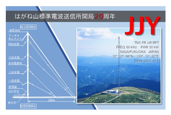
Hagane-yama Standard Radio Transmission Station
transmission frequency: 60kHz, antenna power: 50kW, transmitted power: 25kW


Predicted electric field strength by prefecture
We provide a calculated value for the expected field strength of the standard radio signal depending on the month and the location where the signal is received. The data represents the values for each hour of the day. Please note that the actual received field strength may differ.
After selecting time and location, click "Show data" and a pop-up window will open to display the data. If no window appears, you may need to set your browser to allow pop-ups for this page. If you select "archive of all prefectures", then the data for both signals will be provided as a ZIP or LZH file. If the result indicates "File not found", please try different parameters, the data might not yet be available.
The calculation uses the method described in
N. Wakai, N. Kurihara, A. Otsuka and K. Imamura,
長中波電界強度計算法 / Prediction method of LF/MF field strengths
Technical Report of the Institute of Electronics, Information and Communication Engineers 103(655), 35 (2004)
Predicted electric field strength for an arbitrary location
We also provide access to a Field Strength Pro software that calculates the predicted field strength for a signal of 40kHz to 500kHz at an arbitrary time and location. It is based on the Wave Hop method of
ITU-R Recommendation P.684
for spatial waves, and
ITU-R Recommendation P.368
for surface waves.
Field Strength Pro Ver. 1.0 is free software that was developed for Windows XP systems, but should also operate on later operating systems. It can calculate the field strength within 4000km surface distance from the transmitter.
You can download this software here:
English version (readme)
Japanese version (readme)
The latest version is no longer available for download, and results are instead provided as an automatically generated email.
Field Strength Pro Ver. 3.1 (beta) includes multi-hop sky waves and can calculate field strengths for a propagation distance of up to 16000km. You can access the calculation service
here.
Please consider this software an experimental service that may become unavailable at any time.
Reception reports
If you receive the signal of one of our JJY stations (by radio receiver, radio controlled clocks do not count!), you can send us a reception report and we will return a QSL card. Please make sure that you have received the morse code identifier transmitted at 15 minutes before and after every hour, and then follow these instructions.
We are keeping an overview of
all the reception reports
that we have received from different regions so far.